Grumman F9F Cougar
REVIEW ARF MACKAY F9F GRUMMAN COUGAR EDF By DEREK SMALLEY of the South Norfolk Model Flying Club
· INTRO
Having flown mostly electric since obtaining my A certificate, I was intrigued when Stuart, himself, of Stuart Mackay Models carried out a talk the South Norfolk Model Flying Club at about his range of all-moulded epoxy/glass models he distributes. He brought along the Constellation for four 400 motors and the room filling Katana for large I C (ugh) motors, but I was particularly impressed with the video of the Airworld models, especially with the electric ducted fan F9F COUGER which appeared to fly fast and realistically.
Without knowing all the details except a few basic facts E-mailed to me, I placed my order and sat back and waited.
I already had a Plettenburg HP 290/20/7 and a midi fan from the Electric Model Aeroplane Co.
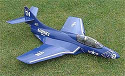
A phone call from Stuart saying the model had arrived had me hurrying to his home to collect it and pay the cash. It was superb, a miniature version complete down to the panel detail and rivets, it looked as if it was travelling at 100mph just sitting on its stand. The model comes in bubble-pack bags which can be used for protection during building and storage. I also bought a 12-cell pack of Sanyo 2400's.
The model is made in their factory in Budapest, Hungary and is one of a large family of similarly constructed scale model aeroplanes (see website details below) just needing assembly, radio and power source, be it electric/PSS or the petrol engines which they sell.
The model comes in four main mouldings, the wing section and lower rear fuselage, the front and top fuselage section, and the two part tailplane, all moulded in aviation grade epoxy and finished in US Marines blue gelcoat complete with decals etc. Ancillary parts include the canopy and frame. A loose top internal rear duct section and machined aluminium rear exit ring completes the parts count. The internal wing mounted intake ducts are pre-installed and blends smoothly into the stepped shoulder to take the selected single 110mm-dia-fan unit, which clicks easily into the preformed recess in the lower fuselage.
The moulding is excellent with detail needing to be seen to be believed. The control surfaces come with gapless kelvar "elastic-flap" hinges ready installed.
The model came with no plan or instructions, and as it is the first in the country, I have volunteered to be the guinea pig to allow Stuart to produce some instructions for the assembly which is obviously not a first R/C model.(and if it is, you are going the wrong route!)
CONSTRUCTION (or lack of!)
A light cleaning up of the top and bottom fuselage mating surfaces to remove the minimal moulding fin is required, and a more vigorous application at the jet tube exit, where the top and bottom fuselage parts, the internal duct and the exit ring come together. (a mini grinder is useful here.)
The control surfaces hinge material is best carefully thinned to allow free movement from the underside, using a small file with the surface bent back to 90 degrees.
It is the builders choice whether they construct the model as a one or two piece aeroplane, I opted for the two piece as I wanted to carry out comparison tests on different fan units and motors, and. I also wanted to have easy access to the internal electrics.
If a one-piece model is required the top and bottom can be siliconed together after installation of the internal parts and electrics.
If, as I did, you want the parts to easily separate, the following slight modifications are necessary. Cut a light ply dummy former to fit inside the front fuselage/wing joint, and drill and insert two small self tapping screws into the front section (through the former) trapping the lip on the lower section. The step in the wing /fuselage joint prevents any upward movement.
Epoxy the aluminium ring to the lower rear fuselage, and drill to bolt or self-tapping screw the top fuselage to the aluminium exit ring.
Along the fuselage sides small patches of Velcro are sufficient.(Stuart suggests that to make a solid joint is inadvisable! A certain amount of flexibility is advantageous)
The two stabiliser parts are joined with carbon fibre rod through a pre-made hole in the fin with two piano wire locators that require holes to be drilled in the fin to retain the incidence. The internal top duct was secured in place using silicon sealant, making sure the top fuselage would still fit.
Recommended servos are mini metal gear type, two required for the ailerons and one to operate the split elevators. I have elected to mount a single elevator servo behind the cockpit in the upper fuselage section. Using a carbon fibre push rod I have connected the elevators with a piano wire Y extension to ball type horns epoxied to the elevators. The aileron servos are installed by cutting openings in the underside of the wing. The servo, preferably covered in heatshrink, can be held in place with silicone directly onto the inner top wing skin. The servo leads need to be extended and routed through to the central fuselage near the fan unit, taking care not to get the wrong side of the spar which runs down the thicker part of the wing. Once the servos are installed, the panel removed can be stuck back into place with Magic Tape or matching solartrim as I did. A small section of the panel is cut away for the servo arm to protrude. Elevator horns from printed circuit board or similar can be made and epoxied into position on the elevator. The connections are made from threaded push rods with a Z bend at the servo arm end and connected to the horn with metal clevises. (Or your personal favourite system) The receiver and speed controller are velcroed to the centre wing section, inside the fuselage and the power connection cables made up. The battery lies in a recess in the front of the wing and is positioned to obtain the correct CG position, which is 175mm(7" ) behind the wing leading edge. I have made a battery tray, which is fixed, inside the nose section, the battery being tie wrapped to this. Crash foam holds everything steady and prevents forward movement of the battery. This just about completes the assembly of the model, now the really interesting bit!
FLYING
For the initial test flight movements on the control surfaces were set as follows:-
Ailerons 10mm up and down
Elevator 6mm up and down
Exponential +20% (elev and aileron)
The CG was double-checked, and a range check carried out at full power, this proved OK.
The first flight coincided with a Sunday electric fly in at the club field at Suton, Norfolk. For the test flight the transmitter was handed to fellow club member Keith Whiddett, an experienced gas turbine pilot. Using an a la Chris Golds type bungee the model was released with the Plettenberg screaming on full power. The climb out was phenomenal!!!!! With Keith having to feed in down on the elevator trim to retain level flight once a safe height had been attained. What followed was a display of climbing turns, rolls and LARGE loops followed by diving passes over the strip. The climax for me was a pass down the full length of the runway at no more than 6 inches height, the comment from Keith went something like "there's no prop to hit the ground" my comment is not printable. At about 6 minutes the power was beginning to fade so the aircraft was lined up and brought in for a smooth gentle landing which had those watching in awe regarding the performance.
· CONCLUSIONS
Well, was it worth it? you bet. The model had all that saw it impressed, and Keith's view was it flew nearly as impressively as his gas turbine models, praise indeed.
I still have to fly it, but the model had no vices and was smooth and steady in the 12knot wind that prevailed that day.
· POWER TRAIN used
| Motor Fan unit Nicads Speed controller Servos 3 no Receiver |
Plettenburg HP290/20/7 WeMoTec Midi 5mmshaft 12cells Sanyo 2400 Schulze50with BEC Hitec HS81MG Jeti 7 |
| Wingspan Length Weight (quoted,12 cells) Weight (achieved, 12 cells) Thrust (theoretical) Thrust (Actual) Speed (quoted) Flight time (2400) |
940mm 1100mm 2.2kg 2.15kg 1.5kg Not measured 100mph 5+ minutes |